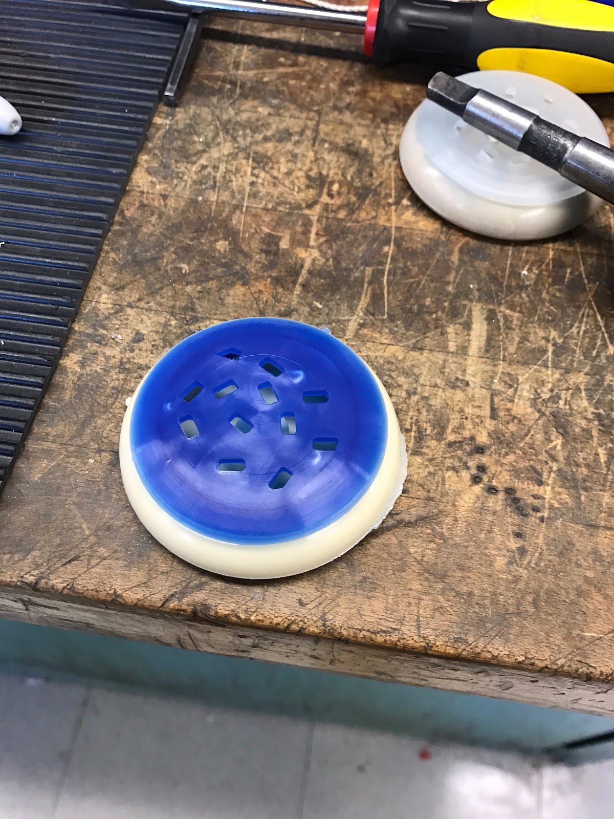
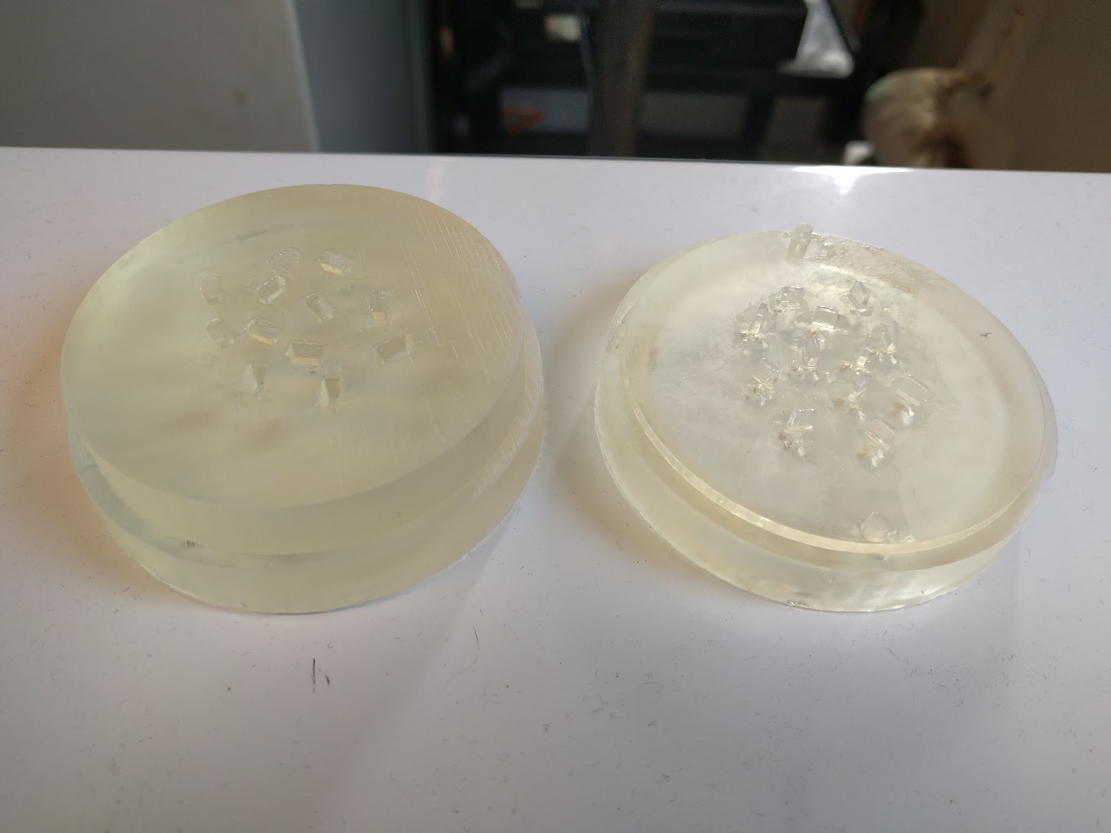
As said before, our yoyo consists of three main parts, the base (or the cookie part) the frosting, and the thermoformed sprinkles. One of the key features we had to watch out for was the frosting and cookie interface as they had to be snap fit. We had to remachine the mold 4 different times, 2 of which was remachining the entire mold. After much adjustment however, our yoyo now passes the drop test (doesn’t come apart when dropped). The snap fit is quite tight though as parts shrink when they cool. A less fitted ring would make assembly a tad easier.
Another key feature is that the yoyo works! In fact, because of the thickness of the cookie rim, the weight along the edge is able to ensure very smooth yoyo-ing.
Table of Specification Limits
Revised Table of Specifications
Dimensions
|
Target Value
|
Value Measured
|
Expected Tolerances
|
Measuring Methods
|
Manufacturing Method
|
Exterior Shell - OD
|
2.5"
|
(+/-) 0.005
|
Calipers
|
Injection Molded
| |
Exterior Shell - Snap Fit OD
|
1.7" (1.75”)
|
(1.744”)
|
(+0.005/-0.000)
|
Calipers
| |
Exterior Shell - Inner Hole Diam.
|
1.5"
|
(1.597”)
|
(+/-) 0.005
|
Calipers
| |
Exterior Shell - Width (1/2 yo-yo)
|
0.5"
|
(0.519”)
|
(+/-) 0.005
|
Calipers
| |
Exterior Shell - Snap Fit Depth
|
0.1"
|
(0.173”)
|
(+0.005/-0.000)
|
Calipers
| |
Exterior Shell - Inner Hole Depth
|
0.2"
|
(0.214”)
|
(+/-) 0.005
|
Calipers
| |
Exterior Shell - Inner Diameter
|
2.2"
|
(+/-) 0.005
|
Calipers
| ||
Exterior Shell - Screw Hole
|
0.2"
|
(+/-) 0.005
|
Calipers
| ||
Frosting - OD
|
2.2"
|
2.267
|
(+/-) 0.005
|
Calipers
|
Injection Molded
|
Frosting - Snap Fit ID
|
1.7"
|
1.644
|
(+0.000/-0.005)
|
Calipers
| |
Frosting - Snap Fit Depth
|
0.1" (0.2”)
|
0.2”
|
(+0.000/-0.005)
|
Calipers
| |
Frosting - Sprinkle Hole Width
|
0.05" (0.135)
|
0.130”
|
(+/-) 0.005
|
Calipers
| |
Frosting - Sprinkle Hole Length
|
0.15" (0.235)
|
0.230”
|
(+/-) 0.005
|
Calipers
| |
Sprinkles - OD
|
1.55"
|
1.5”
|
(+/-) 0.05
|
Calipers
|
Thermoformed
|
String Gap
|
0.1"
|
(+/-) 0.01
|
Calipers
|
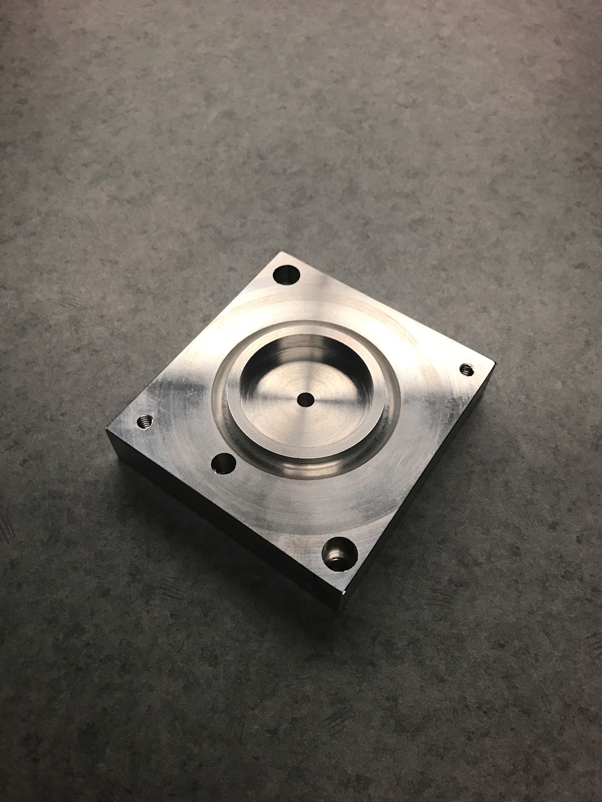
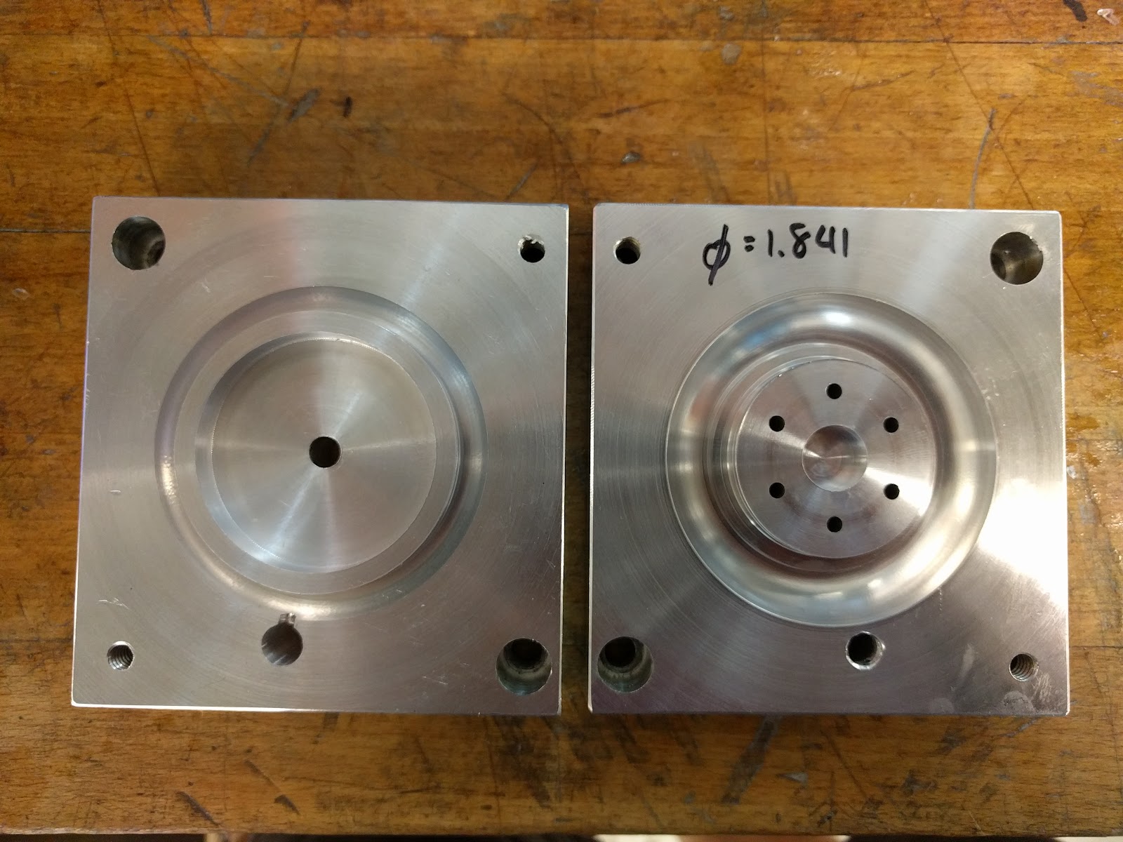
The changed values are in red on the target value column. With our initial injection molded parts, the press fit of the frosting body into the cookie body was too tight. We measured the difference and updated the models to fit this difference (50 thou). We then machined a new cookie core mold and tested this to make sure everything fit properly, which it did. We also realized after doing our initial injection molding that the depth of the press fit on the frosting piece was too small. We put our frosting core mold back on the mill and added 100 thou to the depth to get a better press fit. Finally, to be able to get all of the sprinkles to fit on the frosting and to ensure that they wouldn’t break off, we increased the size of the sprinkles and reduced the number of them.
Summarized findings from written deliverable 4, and linked pdf of written deliverable 4
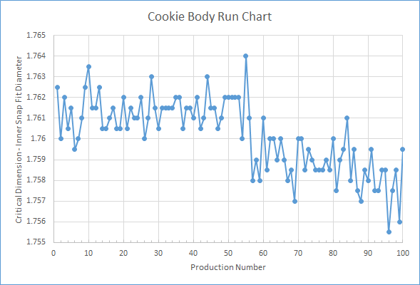
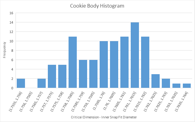
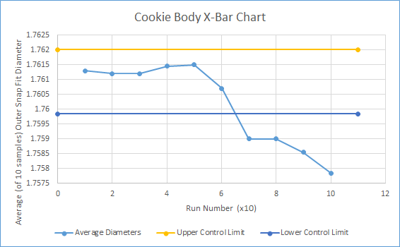
For the cookie body part, the ring diameter for the snap fit was measured and plotted in a run chart and histogram. Halfway through production, a step change was made decreasing cooling time from 20 to 15 seconds. We can see the effect of the change in the run chart. For more information, you can find a link to all three parts (& more!) https://tinyurl.com/n347ehr
Part: Cookie Body
Step Change: Decreasing cooling time from 20 to 15 seconds
Group Video (2-3 minutes)
https://youtu.be/dQw4w9WgXcQ
Cost of Manufacturing
We estimated the cost of manufacturing our YY at a volume of 100 parts (and thus 50 YYs), using the 2.008 materials and processes, to be $62.94 per YY. Compared to a volume of 100,000 parts (and 50,000 YYs), this cost drops to $3.65 per YY. Cost breakdown is shown in the charts below for each scenario:
We’ve made some assumptions about how these processes will change at large volume, assuming that variable costs scale linearly and predictably with volume. We also assume that there are no additional costs associated with the process, and that the machines never fail (not considering cost of tooling or mold replacement, or cost of downtime and repair). We also assume that all materials arrive within spec; we don’t have bad/unusable materials. All of these factors may affect the true production cost for our YY, however they will not affect the general trend for the dependence of YY cost on production volume. This trend is shown in the graph below:
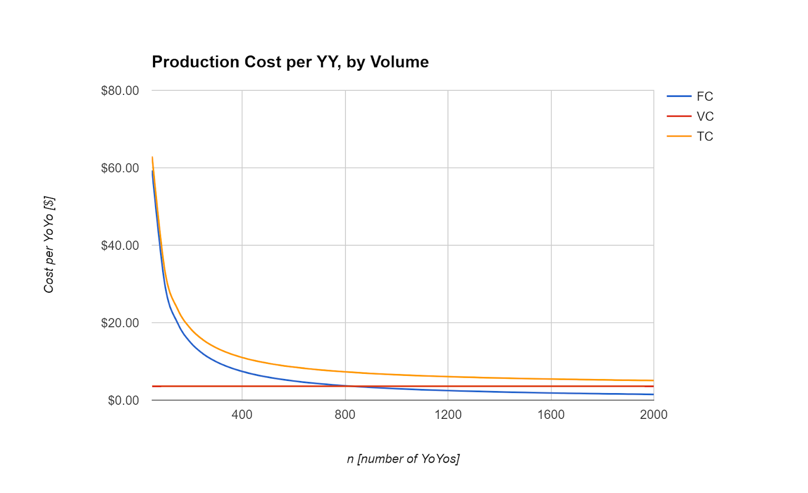
As the production volume increases, the total fixed costs (FC) are divided between a larger number of parts. Thus, as n gets very large, the FCs approach $0.00, and the total costs (TC) approach the variable cost (VC) of each YY.
- Reflect on how your YY design was adapted to meet the constraints of the 2.008 manufacturing equipment, and how you would change it for mass production. You do not need to present a new design, only a succinct description along with any visuals indicating how you would suggest changing the part and/or tooling design to enhance suitability for mass production. You may also mention features that you wanted to make but were prevented by the equipment in the 2.008 shop.
Production Reflection (What would we change on mass production)
- Relocate gate and runner systems to maximize yoyo attractiveness
- Make plastic in certain regions thinner to minimize shrinking defects
- Resize snap fit slightly for easier press fit, or press fit before parts are cooled completely.
Class Recommendations
We feel that the videos shown during lecture really helped to illustrate and explain the various manufacturing processes where a photograph or diagram may not have been as clear. More videos (such as the “How It’s Made” series on youtube) would have helped a lot with understanding various manufacturing processes. We also feel that the yoyo project as a whole was pretty well-organized and a very effective way to demonstrate the key factors being taught in the class. It also allowed creativity of design thinking, especially when subject to the constraints of the class and available machinery. We also liked the connections drawn between the yoyo project and lecture material; for example, we found the cost lecture activity (comparing machining to injection molding cost, etc) very enlightening and would love to see more lecture activities, examples, or comparisons like this one.
Both the paper and blog deliverables were good opportunities for reflection on the process and how we might improve our work in future. It’s true that there was a certain degree of overlap between paper and blog deliverables, but we think that helped us practice synthesizing and summarizing detailed technical information. We might suggest faster feedback on the paper deliverables because getting comments before the next deliverable or next step in the process is finished allows making even more effective progress.
From a design standpoint, we think that instating a mandatory meeting with one of the shop staff to discuss our initial design before moving forward and working on details. This would allow any issues likely to arise during injection molding or thermoforming to be identified and fixed more quickly. Our thinking is that each team would create a preliminary set of models or sketches before this meeting and then discuss their proposed manufacturing process and future goals. We of course were able to make appointments to consult with the shop staff this semester and it was immensely helpful, so we think that making the consultation a more formal step early in the process would benefit future students before they even realize they need help.